Exercise: NodeMCU Blink
Objective
Make a LED blink using the NodeMCU micro controller.
The NodeMCU is a wifi enabled micro controller based on the ESP8266 (version 12E)
chip. The NodeMCU is low cost and can be programmed using the Arduino IDE. Like
other Arduinos, it has GPIO pins that can be used to read sensors and control
actuators. Most Arduino sketches (especially all of the basic examples)
should work with minimal modification on the NodeMCU. Additionally, libraries have
been developed to allow the NodeMCU (and any other ESP8266 based board) to
send and recieve data over wireless.
While the NodeMCU has a fair number of digital pins, it only has 1 analog pin.
Watch out for that when designing your projects; if you need more than one analog input pin, you will need to use an I2C ADC board.
Additionally, many external ADC boards communicate via I2C which is not listed on the
pinout diagram. However, D1 (GPIO 5) is SCL and D2 (GPIO 4) is SDA which makes sense since
the Arduino’s I2C lines are A5 for SCL and A4 for SDA.
Unlike the Arduino Uno, the NodeMCU uses 3.3V logic. This means that the GPIO pins output
3.3V and can only tolerate up to 3.3V for input. This is why we don’t need a resistor in
series with our LED in the circuit. However, this means that any external chips you hook up
MUST be 3.3V or you will need to use a logic converter (also known as a level shifter).
All this does is take 5V and converts it to 3.3V and vice versa. You may need to use a logic
converter in order to have a high enough voltage to turn on some transistors. Double check
this if you need to drive a transistor using the NodeMCU.
Steps and observations
- Before anything, on Mac you must install the device drivers from here. If you plan on installing macOS Sierra, you NEED different drivers (at least for the near future). You can download those here. Without this driver, macOS will kernel panic (if you installed the other drivers and are experiencing kernel panics, come talk to us and we will help you fix it).
- First we need to get all the libraries for the NodeMCU so we can program it from
the Arduino IDE. This process is the same for many boards that use the Arduino IDE
(the URL in the next step changes for other boards).
- Open the Arduino IDE, and go to: Arduino->Preferences (Mac) or File->Preferences (PC),
and add this URL: "http://arduino.esp8266.com/stable/package_esp8266com_index.json"
into the “Additional Boards Manager URLs” box.
- Open Tools->Board->Boards Manager and scroll until you find the
“esp8266 by ESP8266 Community” package. Click on it, and install the latest version.
There should now be a new section under Tools->boards that lists several ESP8266 boards.
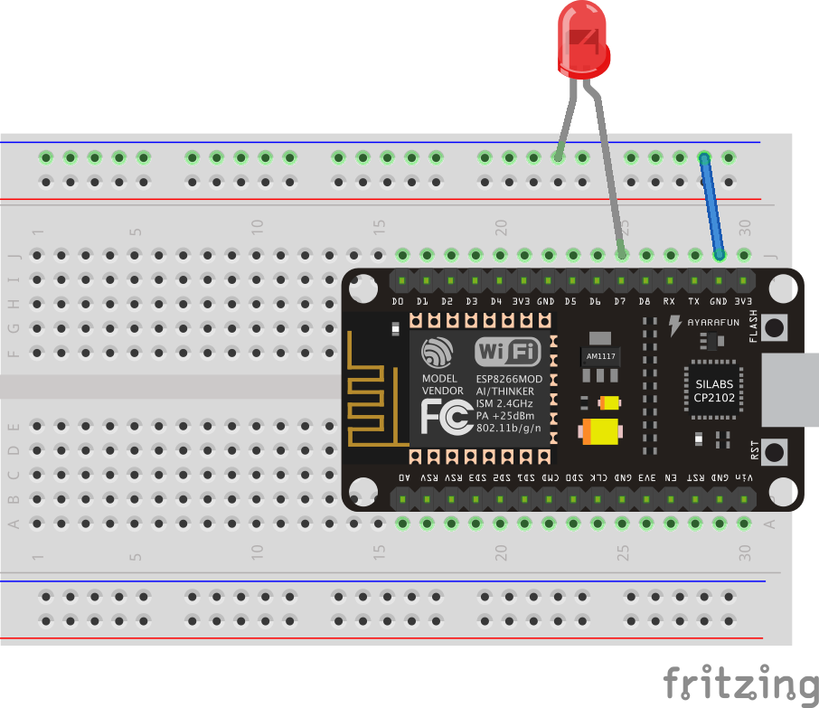
- Build the circuit shown below.
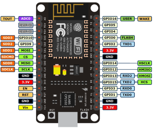
Note 1: the Pin Numbering of the NodeMCU: each pin has a name that's printed on the circuit board, like "D0", "D7", "RX" or "TX". Each pin also has "GPIO" number; if you look at the diagram below, you will see that "D7" is equivalent to GPIO13. This means that in the Arduino IDE you can control the state of that pin using the pin number 13. For all the GPIO pins, you can also type the name of then (i.e. "D7") into the Aduino IDE and the compiler for the NodeMCU will know
to switch this to 13. In other words, either of these will work:
pinMode(D7, OUTPUT);
or
pinMode(13, OUTPUT);
Note that writing the pin name (i.e. "D7") only works for the GPIO pins, and not for the special pins like RX or TX.
Note 2: use #define statements at the top of your
code to define all of your pins with intelligable names (see: #define reference)
- Open the Example Blink sketch (File->Examples->01.Basics->Blink). The defaul pin number 13 is in fact the same as "D7", so you can leave the code unchanged.
- Under Tools, change the board to “NodeMCU 1.0 (ESP 12E Module)” (NOT “NodeMCU 0.9 (ESP 12 Module)”!!!).
You should see some new options pop up in the tools menu. You can leave these as the defaults
(should be: 80MHz CPU Frequency, 4M (3M SPIFFS) Flash size, and 115200 upload speed).
- Also under tools, check the port. Choose whatever is available (should be a non-bluetooth port on Mac,
or something like COM4 or COM_something on PC). If there is no port available, or the one you have doesn’t work,
then you need drivers for the USB to serial chip.
- Hit upload, wait for it to finish, and you should be done. Note that a small surface-mount blue LED near the end of the board flashes while you are uploading code to the board. You may have to press the "RST" button on the NodeMCU to get the new code running.
Comments
- The NodeMCU is a more affordable, more capable and more practical version of the popular Adafruit Huzzah. If you run into problems with this board, you can often find the answer if you search the same problem with the Huzzah.
Other Files
- NodeMCU-blink.fzz