Exercise: Stepper Motor Knob
Objective
WARNING: this exercise has been known to have bugs in the circuit and the code.
If you would like extra credit, submit a bug fix to some or all of the issues you
find.
Control a stepper motor using a driver module.
A stepper motor
uses a toothed rotor and multiple drive coils to create motion in discrete
steps. The fundamental angular size of the steps is determined by the
physical spacing of the internal magnetic teeth. Steppers motors
are open-loop since there is no sensor involved in controlling
position, the driver simply cycles the coil currents and assumes the motor
moves synchronously. If the motor encounters too high a torque, the
magnetic forces can be overcome and the rotor will slip to a different
position. The microcontroller has have no means of detecting this
error.
This exercise uses
an
stepper motor driver module which takes care of cycling the currents
appropriately through the two coils of a bipolar stepper motor. The
primary inputs to the driver are direction and step.
The additional inputs control fractional stepping and the overall driver
power state.
As a simple one-in one-out demonstration, the exercise uses a
potentiometer as an analog position command control input.
Steps and observations
- Use a DMM to measure the winding resistance of the stepper motor. A
bipolar stepper motor will have two independent windings which should be
clearly observable as a low resistance between two separate wire
pairs.
- The lab stocks several different kinds of stepper motors and stepper
motor drivers. Please check the motor type; it should have a rated
voltage lower than your supply voltage. These drivers control the
current by chopping the power supply, so the supply voltage can be
higher than the motor rating. If the chosen supply voltage is less than
8V (e.g. 2.7V), you will need to use
the low-voltage DRV8834
stepper motor driver. If the supply voltage is more than 8V
(e.g. 10-12V), you should use
the A4988 stepper motor
driver, which is a newer replacement for the
A4983.
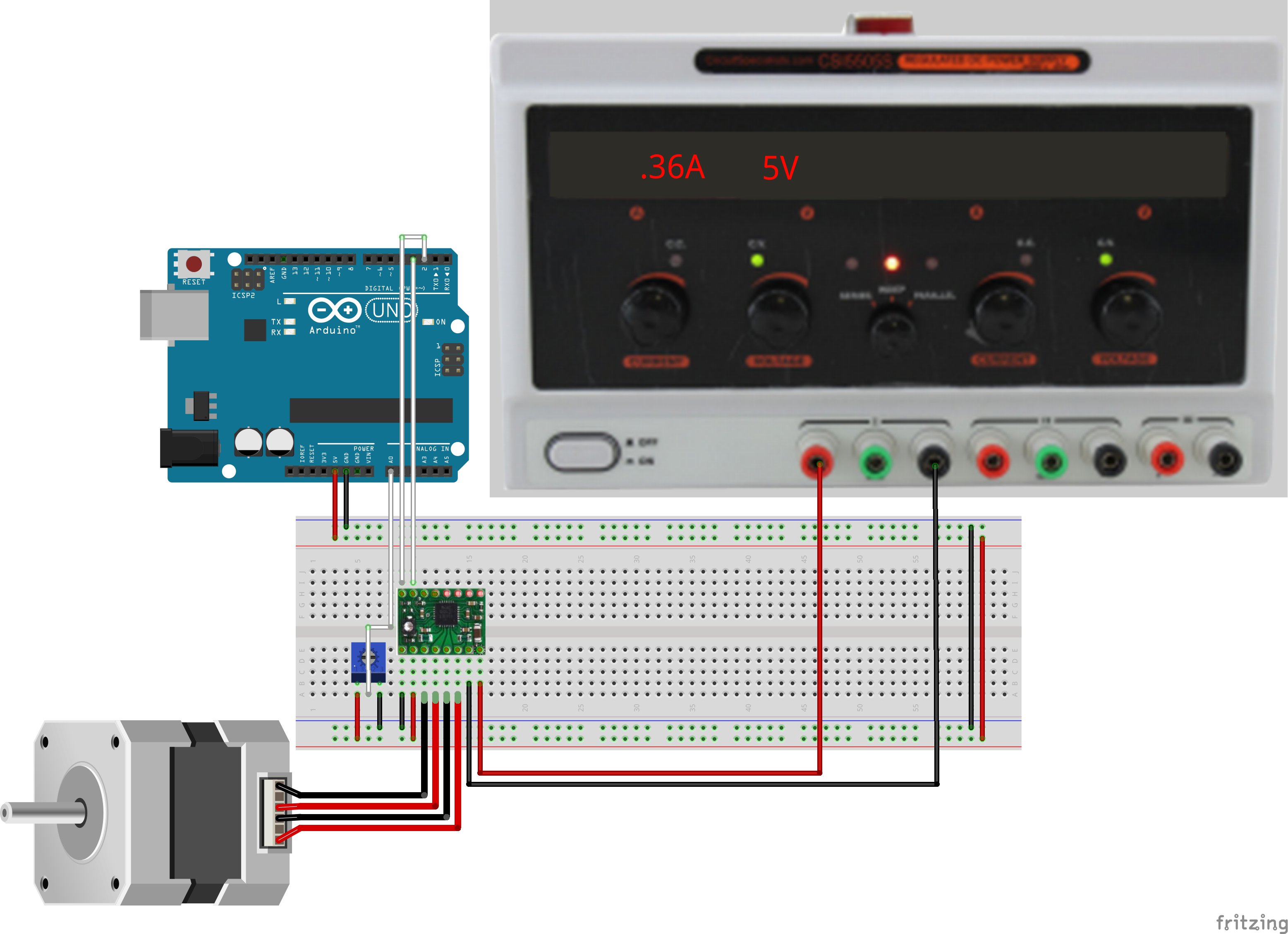
- Load and run the KnobToStepper sketch from the course materials,
located in the same folder as this file if you have cloned the github distribution. If not, it is
directly
downloadable. (Note: there is a MotorKnob
sketch included in the Arduino IDE which assumes the stepper motor is
directly driven from the Arduino; instead we will use a modular driver
for this exercise.)
- Observe the stepper motor motion.
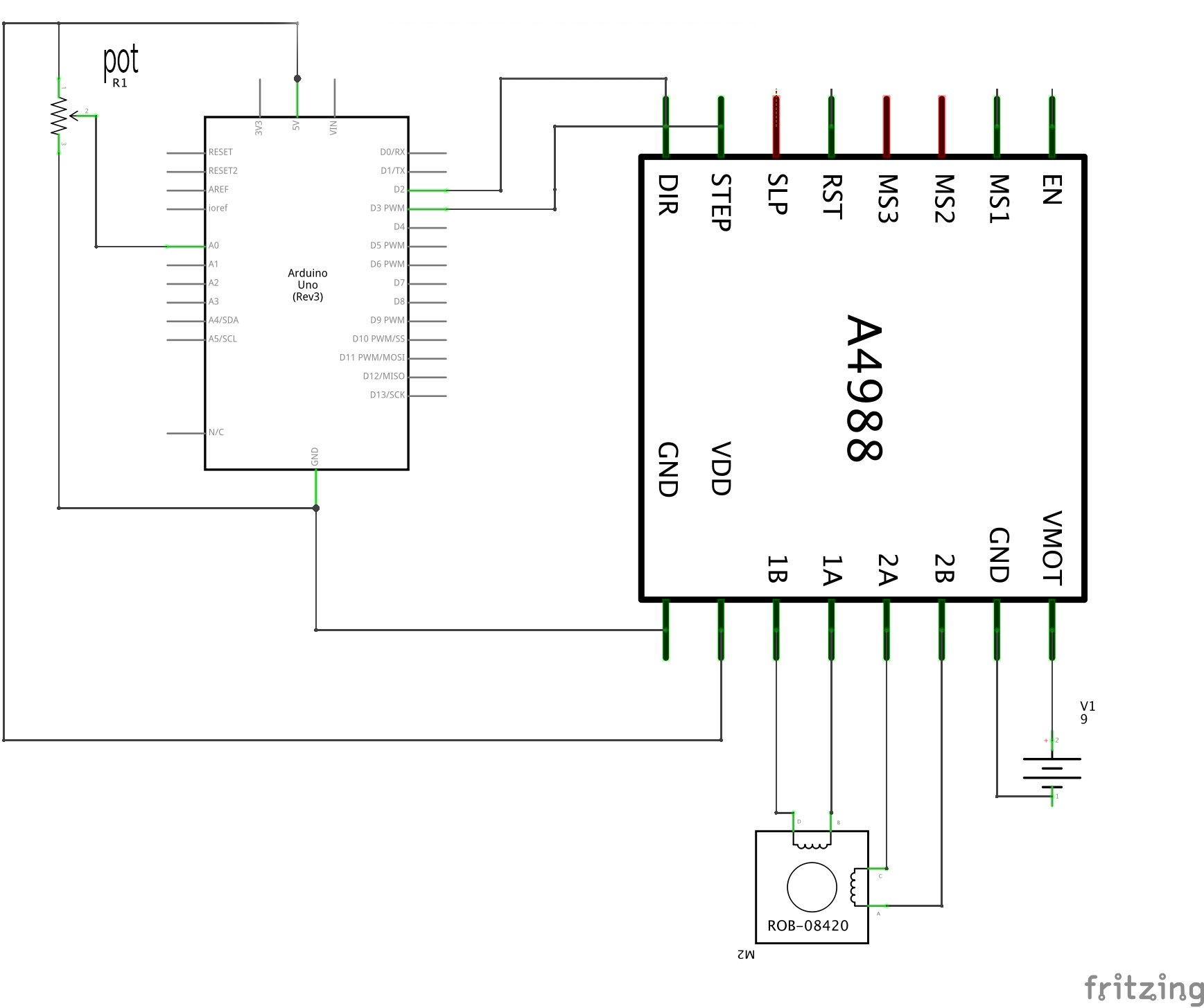
- Try moving the MS1 pull-up resistor between 5V and GND and observing
the resulting change in step rate. The driver is capable
of microstepping in which the coils can be driven using PWM
rather simply on or off in order to divide the fundamental step into
smaller angles.
- Read the data sheet for the driver and configure the driver for even
finer steps.
Comments
Stepper motors can move relatively fast but at too high a rate can lose count.
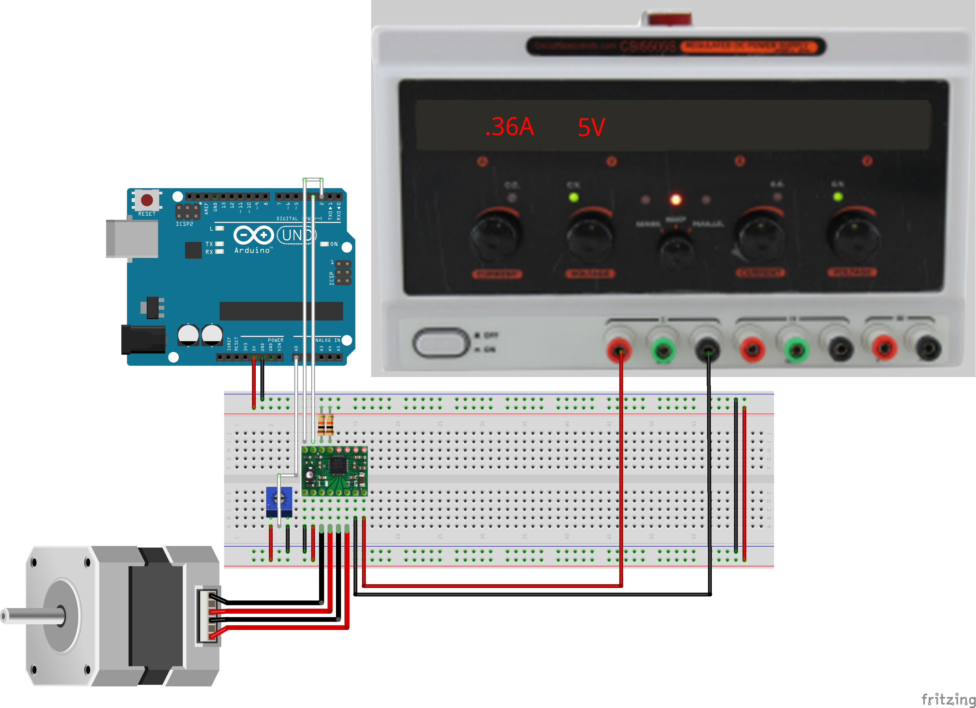
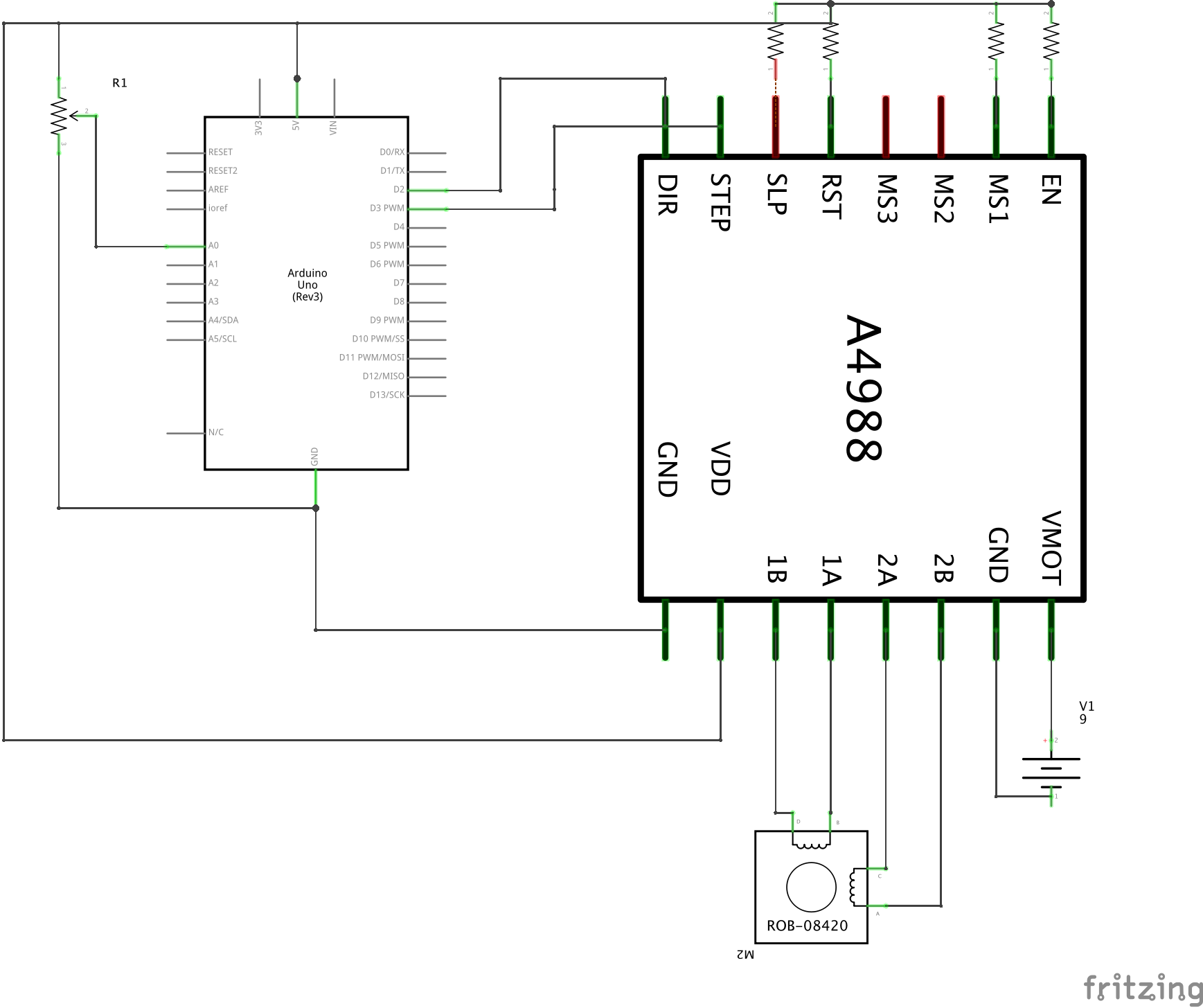
Note: The following diagrams were tested with a polulu DRV8834 Low-Voltage Stepper Motor Driver Carrier. There may be some different versions of this, or other, stepper motor drivers from polulu in the lab. If the code in these diagrams do not work, you may need to float some of the pins high, as shown in this diagram and schematic.
Other Files
- stepper-motor-knob.fzz
Sub-Folders
- KnobToStepperMotor