Use basic digital I/O on a Raspberry Pi from the command line and Pd.
This exercise assumes you have the basic Raspberry Pi materials as specified in 1.c.iv.1, as well as the following materials:
The Raspberry Pi B+ we have in stock include 40-pin header with a number of digital I/O pins, including I2C and SPI busses. One pin (GPIO18, pin number 12) can generate high-frequency PWM signals. Analog to digital conversion can be performed by attaching an external ADC via either SPI or I2C.
We are using the wiringPi interface
library for convenient access to this hardware interface.
The gpio command-line program is a quick way to inspect and
configure the state of the interface. We also provide
a pdwiringPi external
for Pure Data for basic access from Pd patches. For more advanced
usage, we provide
the WiringPi2-Python
module for hardware access from Python scripts. It is also possible to
write C/C++ programs which directly use libwiringPi.
The gpio command. The simplest way way to see what
the gpio command can do is just run it; it will print out a
list of options. The gpio readall command will show a table
with the current state of all the interface pins.
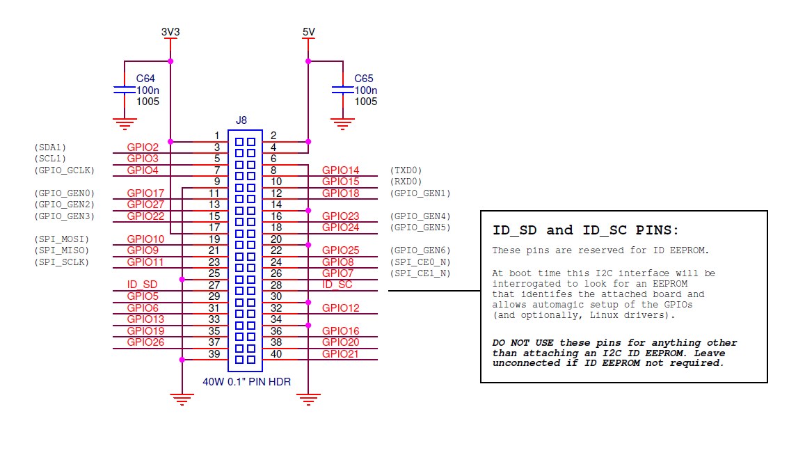
Pin numbering. There are three different ways that the pins are numbered, which can be confusing. The physical pins numbers are defined by the 40-pin header in the conventional order. The CPU defines a numbering based on the internal GPIO device registers; these are referred to as the Broadcom or BCM numbers by wiringPi, but are shown as GPIO on the Raspberry Pi diagram.
Confusingly enough, the wiringPi library and gpio command define another pin numbering scheme, show in the readall display as the wPi columns, next to the BCM columns showing the Broadcom hardware scheme, and the Physical columns at the center with the the physical scheme.
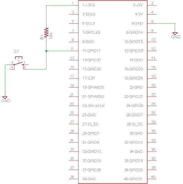
Reading an input. Set up the circuit in the associated diagram with a switch and pullup resistor attached to physical pin 11 and 3.3V. Note that the Raspberry Pi is a 3.3V device, so digital inputs should not exceed the 3.3V supply voltage.
Then try the following:
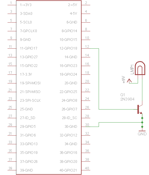
gpio mode 0 inputgpio read 0Configuring a digital output. The following steps will control a lightbulb on physical pin 12/BCM 18/wPi 1. The Pi doesn't provide enough current or voltage for the lightbulb, so you will need to use an external power source with a 2N3904 transistor. Connect the base pin of the transistor to physical pin 12 from the Pi. Then try the following:
gpio mode 1 outputgpio write 1 1gpio write 1 0Configuring a PWM output. Using the same circuit, this will configure the pin for PWM output for variable brightness:
gpio mode 1 pwmgpio pwm 1 512Using wiringPi from Pd. Find the associated Pd patch and run it
as follows: sudo pd rpi-pdwiringPi.pd. Pure Data
needs to be launched with root privileges for fast hardware access. The
text within the patch explains the next few steps, which replicate the
previous steps within Pd.