Visualize physical state data in Pure Data, transmitted from an Arduino using the USB serial bus.
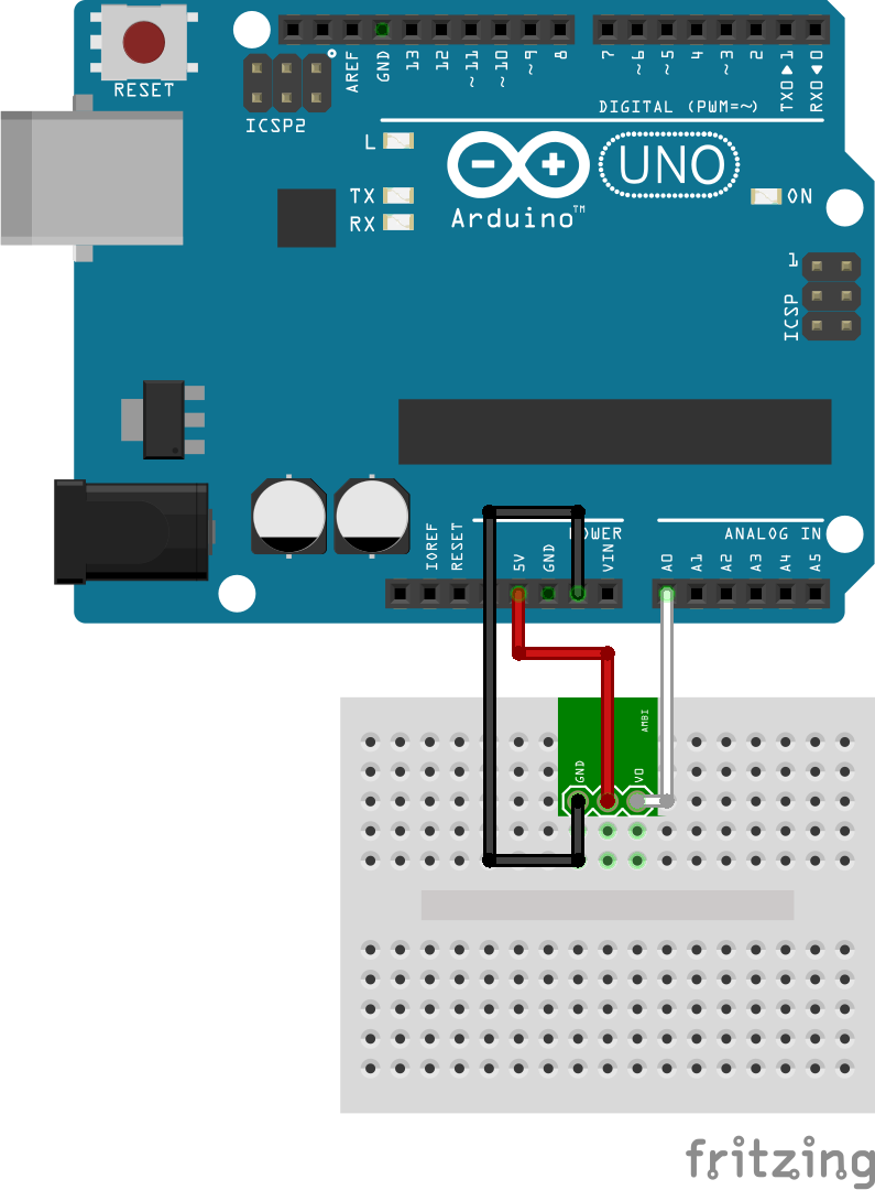
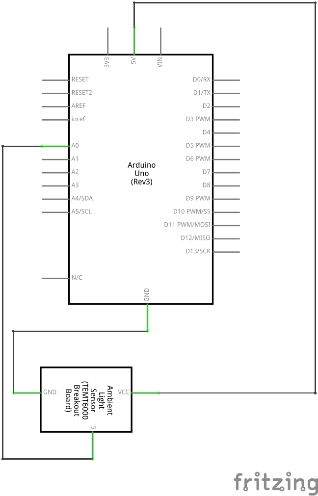
Please review the notes for 1.c.ii.1 as all of them apply to this exercise as well. This exercise assumes you have an Arduino programmed with the OneInOneOutASCII sketch to communicate physical data to and from an Arduino.
The Pd patch is available in the same materials folder as this file. Note that there are two .pd patch files; the Arduino interface has been moved into an abstraction named Arduino-server.pd. This is a reusable patch which hides the details of the Arduino interface; this is the primary means in Pd for building modular systems with reusable parts.
For now, the Arduino abstraction is included with the exercise, but in general re-usable patches should be placed in a library folder included on the Pd load path.
For a challenge, try creating a 3D display.