Drive a light bulb from an Arduino program.
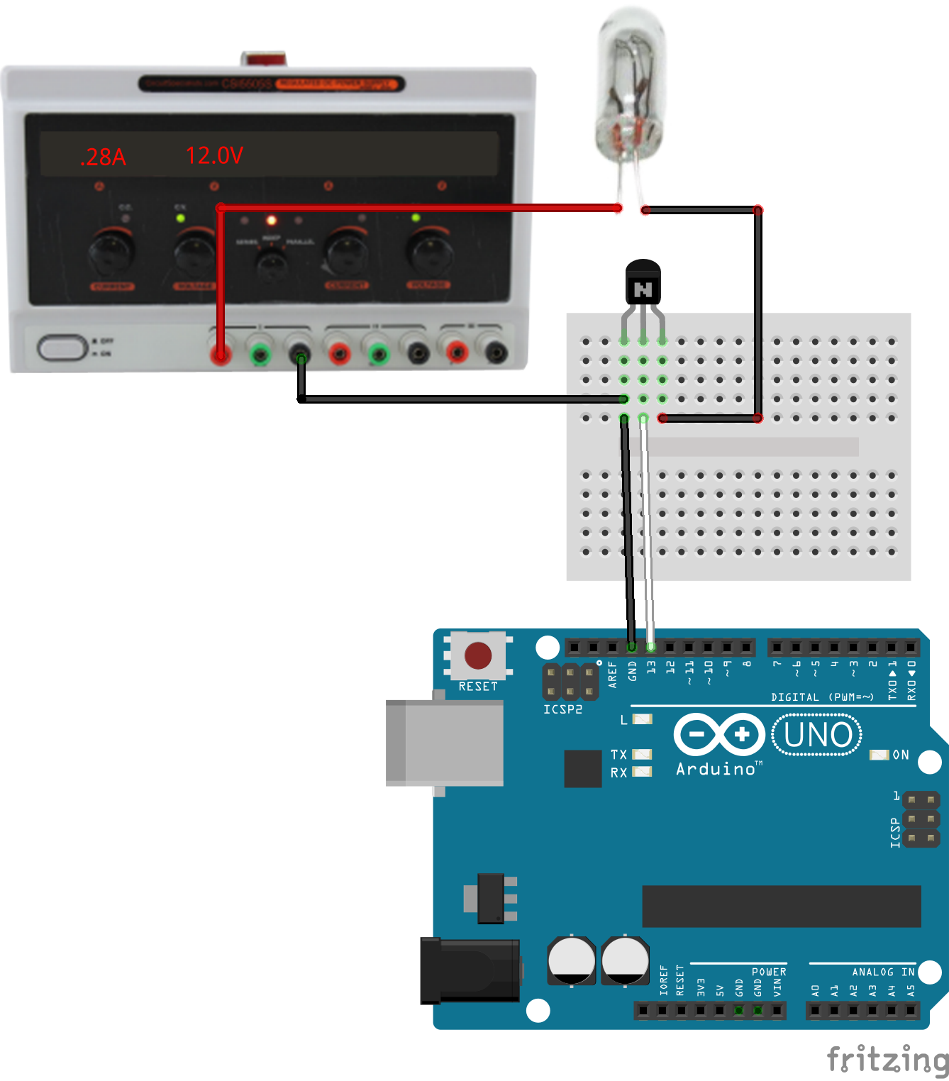
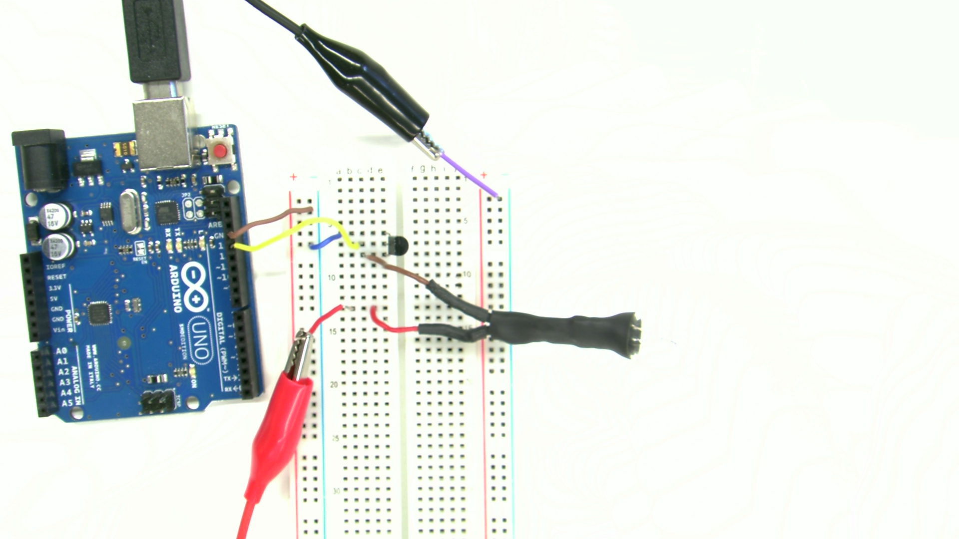
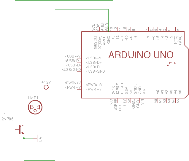
A microcontroller isn't very useful without some kind of hardware attached. This exercise introduces driving an incandescent bulb from a digital signal. The transistor is used as a switch to control a higher current flow through the bulb than the Arduino output pin can sink, and at a voltage unsafe for the Arduino.
digitalWrite() and delay() statements to create a different blink pattern.This simple example cannot drive two separate patterns on two pins
simultaneously, since it just stalls during delay(). Much of
the challenge of programming a multi-function Arduino program comes down
to structuring control flow so the program never stalls so it can service
multiple inputs and outputs simultaneously.
For a challenge, restructure this program to use millis() to
test for the loop cycles on which to change the output state, then add a
second channel of output with different timing. This will covered in more
detail in a later exercise.